Safeties
Safeties (Sicherungen)
By Larry B. Schuknecht
Webster’s Dictionary defines a Safety as “A protective device to prevent accidental discharge”.
The development of the practical Safety on firearms dates back to the first half of the 17th Century and the development of the Flintlock. With the Flintlock a horizontal sear became common which engaged a tumbler with one notch, on which the cock or hammer was mounted . By 1648 when the french Army adopted a flintlock a second notch was added which not only engaged the sear but locked their engagement. (Source- The Flintlock: its origin and development by Torsten Lenk) This is the half cock notch as we know it today. It allows a shooter to carry a flintlock, percussion or early hammer breech loading gun with the hammer or cock in a middle position safely and at the same time ready to be moved to a full cock position.
While the half cock notch continued in use through out the muzzle loading period, with the adoption of the percussion lock came another safety feature. This I call a Hammer Rest. These Hammer Rests take two forms, one from the front of the lock hinging back to fall between the hammer and the nipple. The German term for this is a Pistonsicherung which in English means simply Nipple Safety. These were used on both Military and Sporting Arms.
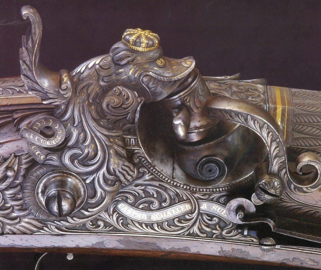
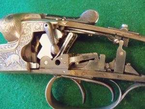
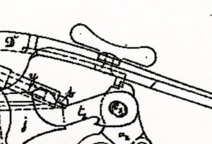
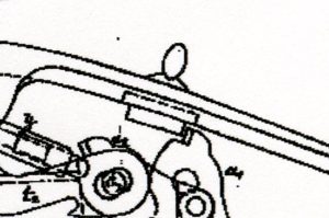
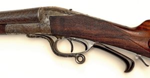
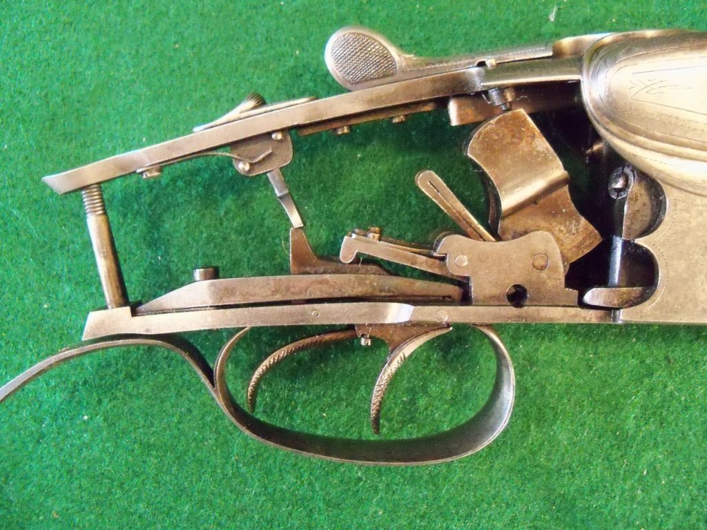
The second type of hammer rest is mounted in front of the hammer and is pivoted to limit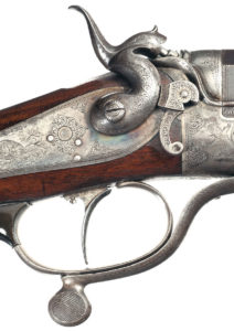 the hammers travel. In German this is called the Hahnsicherung or intrepreted to English would mean a Cock Safety. In German a hammer is reffered to as a Hahn or Cock as in a Rooster. This was used on both percussion and breech loading hammer guns. See the picture to the right.
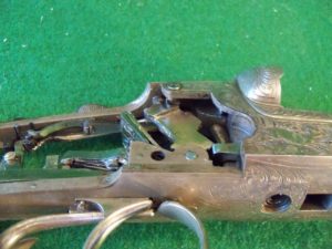
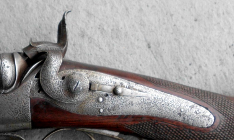
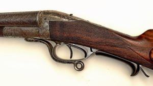
With the common use of the outside hammer breech loading gun came another hammer safety called the Sliding Hahnsicherungen or Sliding Safety or in England called Hammer Blocks. The hammers on these Locks are called Blocked Hammers. See the picture below that is coutesy of my friend Axel Eichendorff.
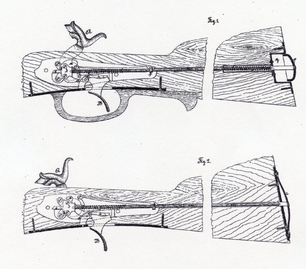
During the second quarter of the 19th Century the development of the needle fire breech loading gun by Johann Nicholaus Von Dreyse brought about a shift in both gun and ammunition design. The side by side needle fire gun did not have a hammer but a coil spring powered needle striker. This spring and striker were housed in a sliding bolt. The bolt also contained a flat spring which acted to hold the bolt in one of two positions. In one position the bolt was to the rear of the receiver and the coil spring was relaxed or in what could be considered a safe position. When the Bolt and this flat spring was pushed forward into the receiver to the second position the coil spring was compressed thereby arming the needle or striker to fire when the trigger was pulled. By pressing down on the bolt’s flat spring the bolt could be returned to the first position making the gun safe again.
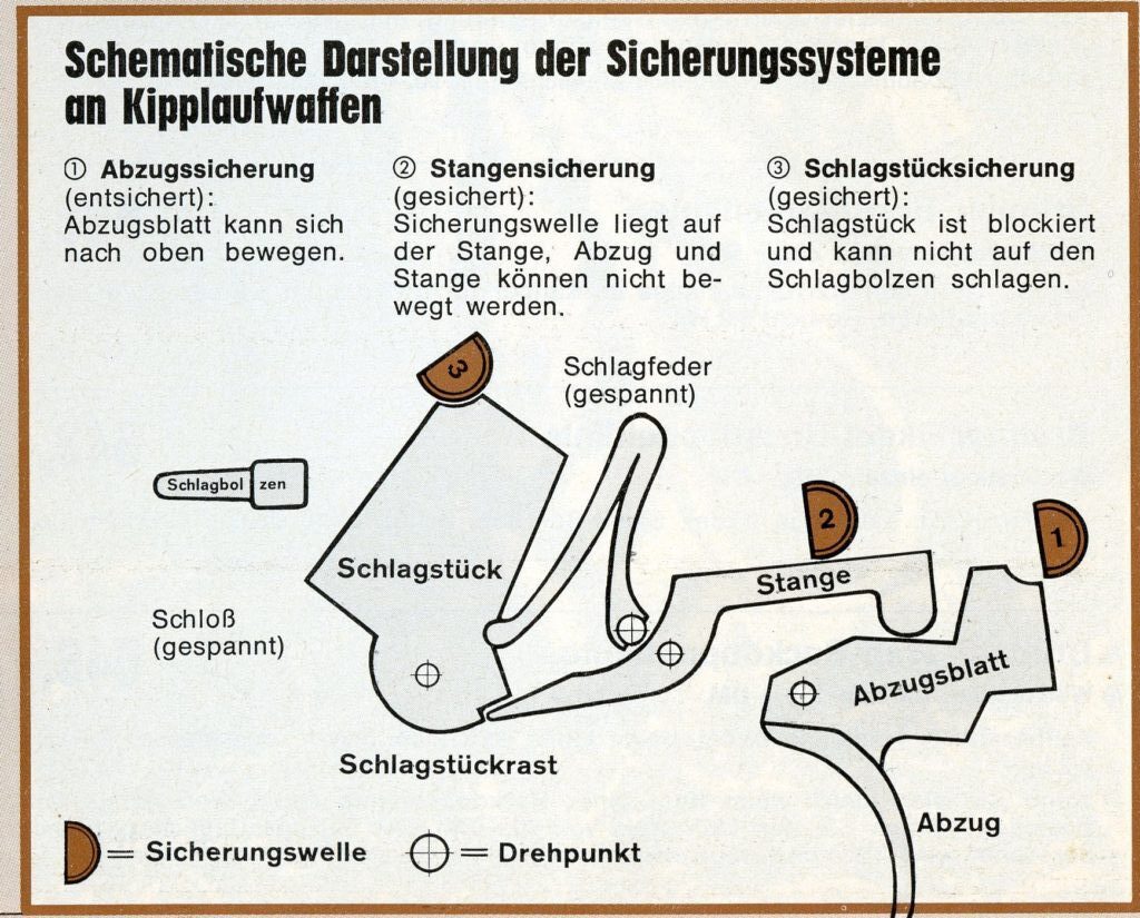
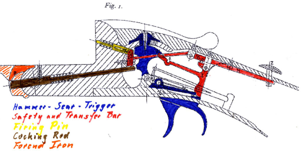
With the development of the Hammerless or enclosed hammer gun in the third quarter of the 19th Century new designs of Safeties became necessary. Three basic types of Safeties emerged. On Break Open or Kipplauf guns they are- 1. Trigger Blocking (Abzugeeicherung), 2. Sear Blocking (Stangensicherung) and 3. Hammer Blocking (Schlagstücksicherung). We will look at no. 3, Hammer Blocking Safeties first because they were the earliest type.
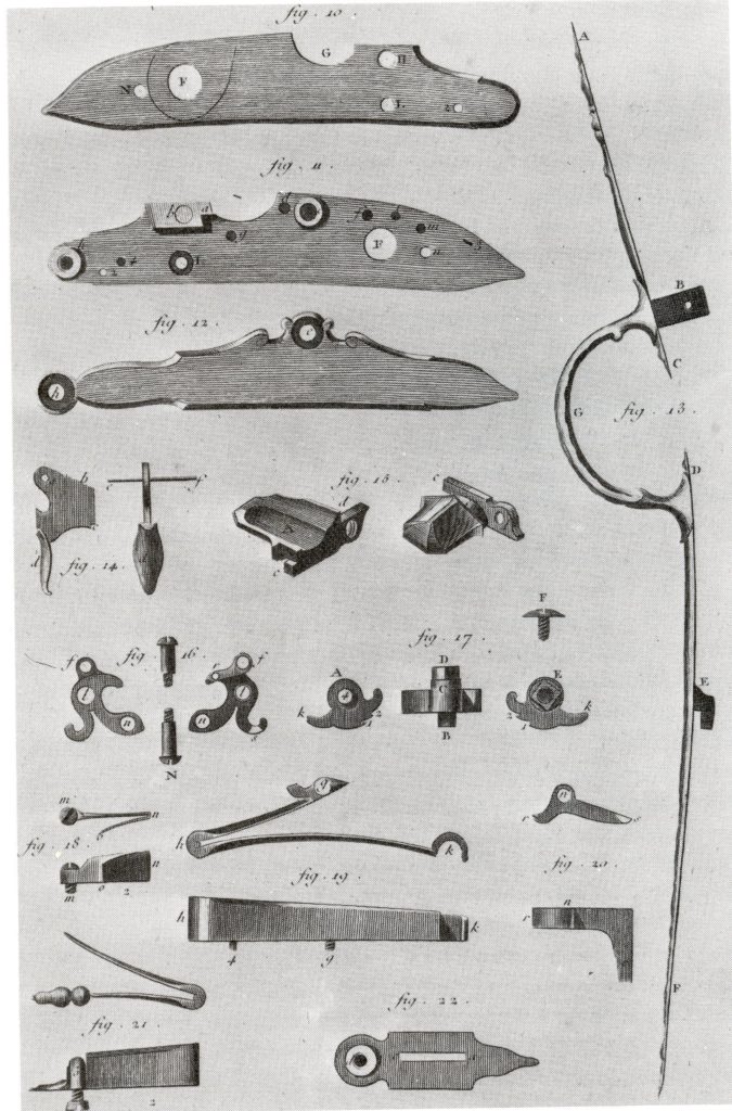
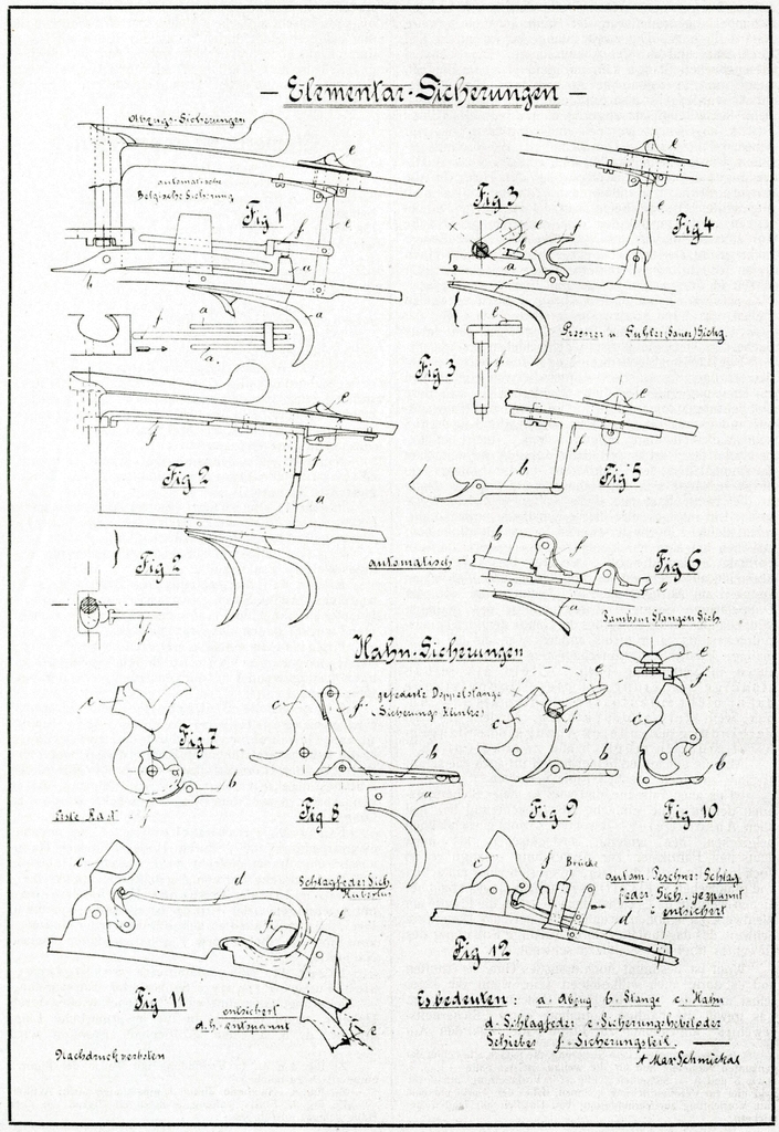
The following image was found in a Die Büchsenmacher und Waffenhandler from 1911.
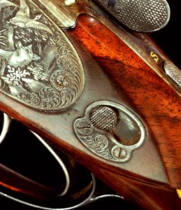
One of the early successful hammerless breech loading designs was that of G. Teschner & Wilh. Collath. They were one of the first inventors to incorporate a Safety on the top tang. This is often referred to as a “Butterfly” Safety since the button has wings which resemble those of a butterfly. When the button is turned so that the wings are in line with the tang the hammers are blocked from moving and when the wings are at right angles to the tang the hammers are not blocked and are free to fall.
Some gun makers designed their actions to incorporate more than one aspect of Safeties. One of these was Wilhelm Brenneke. His design which was patented in 1896 (DRP 94620 & DRP 95046) incorporated four differant aspects, two of which acted on the hammer, one blocked the sear and one blocked the trigger. To read more about Wilhelm Brenneke and his achievements click-Here.
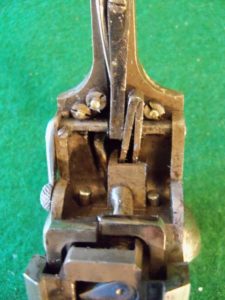
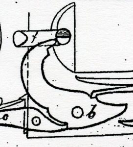
Another Company that used a multiple Blocking Safeties was Greifelt & Co. of Suhl. One system for their Drilling blocked both the hammer and the trigger. In one (shown below) the hammer was hooked from above.
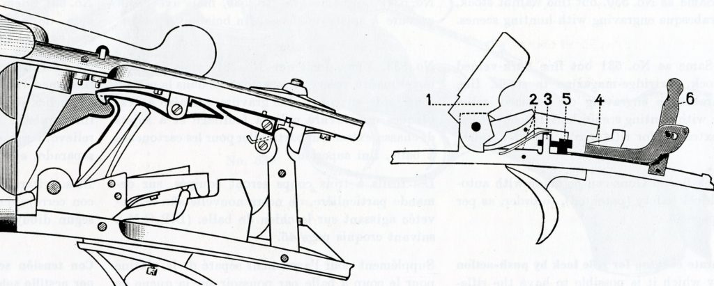
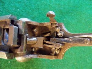
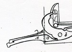
In a second Greifelt design (shown below) both the hammer and trigger are blocked but the hammer is blocked from below.
To read more about the Greifelt Co. and their guns click Here.
Two of the most often encountered safeties were both of the Type 1 and were both designed and patented in England by Englishmen. The later of the two is the Anson & Deeley safety that was covered by British patent no. 907 of 1879. Developed by the two famous firearms designers William Anson and John Deeley, it was recognized both in England and the Continent as a simple and practical safety.
The Anson & Deeley mechanism consisted of an L shaped linkage that rocked a pivoting block which when applied firmly held down the trigger blades.
The second safety widely used in both England and the Continent was the W. W. Greener safety patented in 1877 as no. 1623. It used a transverse rod which rotated and had a cut out portion so that when the lever on the end of the rod was turned, the triggers were allowed to move and trip the sears. This safety was often incorporated into Drillings where the button on the top tang was used to swith the firing from the shotgun barrel to the rifle barrel.
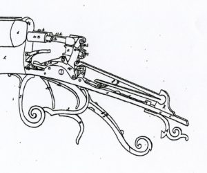
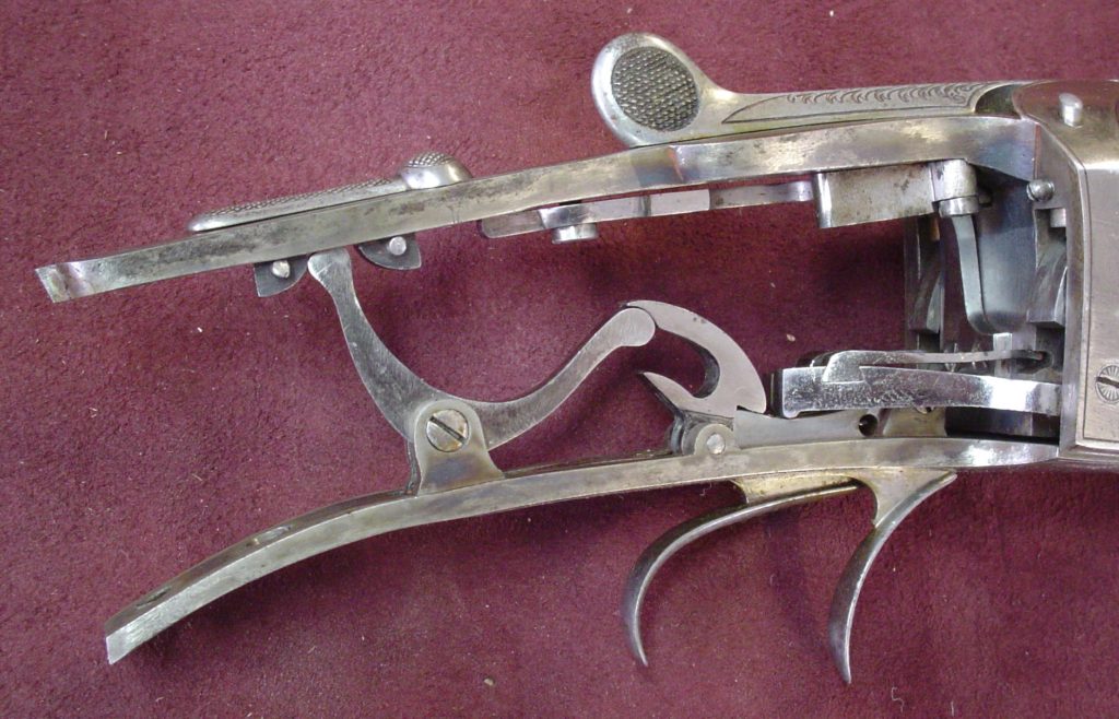
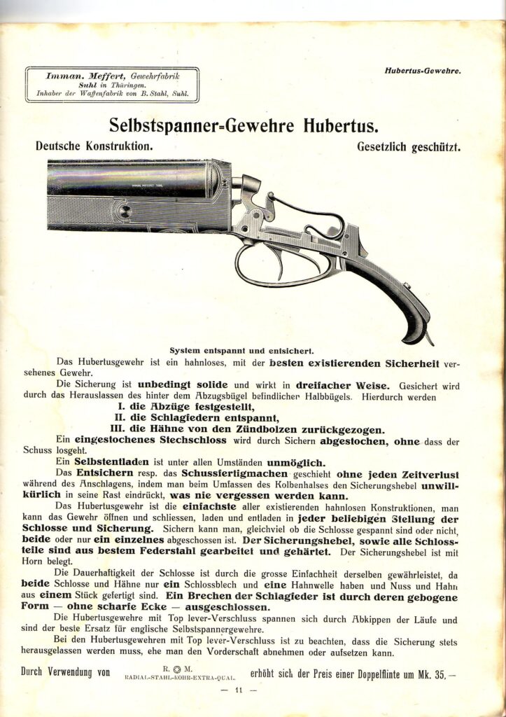
On Nov. 25, 1879 Franz Feist of Sommerschenburg in Wefensleben was issued DRP no. 7142 for a safety which did not perform as the three types previouasly mentioned but acted upon the main spring . In the safe position a lever behind the trigger guard was allowed to drop which relaxed the main spring. When the lever was raised to the firing position the mainspring was put under compression. This safety design was adopted and refined by the Immann Meffert Co. and marketed under the trade name “Hubertus”. To read more about Meffert click Here .
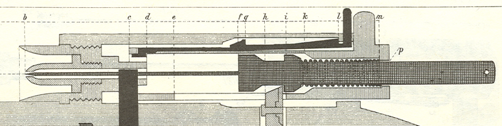
On April 28, 1879 Imman. Meffert was issued DRP 4770 for a action design which included a type 3 hammer blocking safety. This type 3 safety consisted of a transverse rod which passed through the standing breech with a lever on it’s outside end which facilitated it’s rotation. It had flats which would when the lever was set in a horizontal position allow the hammer nose to pass but when the lever was set in a vertical position would block the hammer nose in it’s travel. Franz Jaeger also made guns incorporating this safety design.
![]()
Another type 3 hammer blocking safety was patented by Ludwig Krieghoff on May 2, 1892. This consisted of vertical rods which were linked to the triggers. In the safe position they engaged the firing pins to block thier travel. When the trigger was pulled the rod withdrew from it’s engagement allowing the firing pin to move when struck by the hammer.
In 1881 August Gerken of Berlin was issued DRP 11948 for a type 3 hammer blocking safety which incorporated a rod which linked a tumbler stop in the lock to a pad or plate in the butt which when put against the shoulder moved the tumbler stop to allow the hammer to fall when the triggers were pulled. Several makers used variations of this design and some of them blocked the triggers rather than the hammers.
In the late 1870’s and 1880’s many efforts were made to develop a practical trigger blocking or type 1 safety. One of these was patented by J. F. Timpe of Berlin on March 4, 1885 as no. 30549. It consisted of a pad or lever behind the trigger guard which when compressed moved a slide away from the trigger blade.

Another type 1 trigger blocking safety was patented by August H. Schilling of Suhl on January 16, 1879 as patent no. 3540. It consisted of a sliding button behind the triggers within the trigger guard. 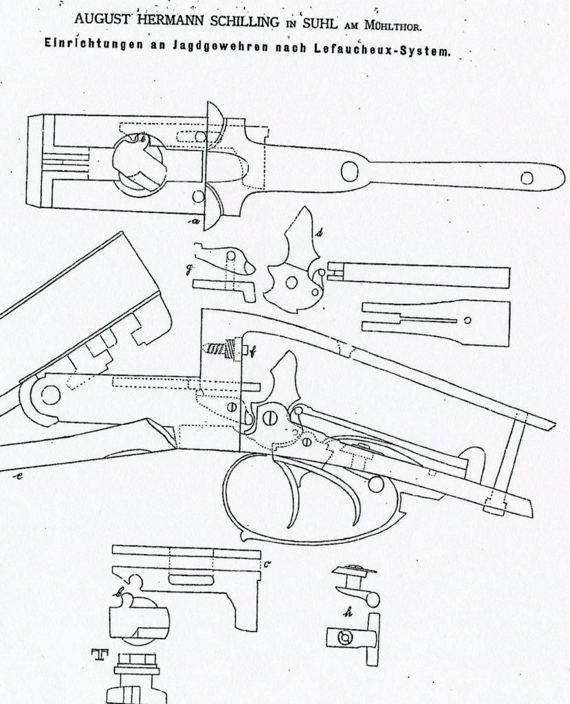
At this point I will conclude the discussion of the type 1 trigger blocking safeties with a look at a “Herkules Verschluß” made by August Schuler in Suhl. It is the simplist form of that type and one that could not be improved upon thus showing that “simple is usually better”.
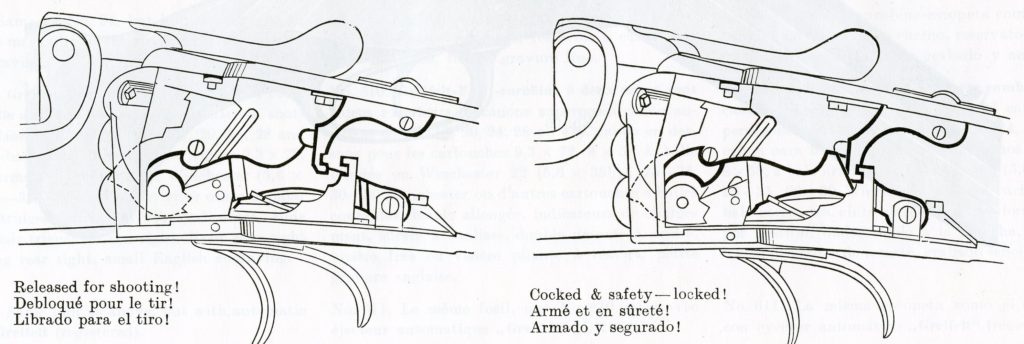
Often on Drillings you will find a Type 2 safety that blocks the rear trigger when the front trigger is used to fire the rifle barrel while it has a Type 3 safety to block the shotgun hammers when using as a shotgun. Below are pictures of a Thieme & Schlegelmilch “Nimrod” Drilling with both a Type 2 trigger blocking safety and a Type 3 Hammer blocking safety.